Post: Arduino PWM over 50Hz
How to generate a PWM signal in phase with a 230v 50Hz AC
In this article we’ll see how to generate a PWM signal with an Arduino digital pin without using the default clock frequency. I’m using a Seeeduino Lotus board based on ATMEGA328P-MU. The goal of this PWM signal is to control a SSR (Solid State Relay) to modulate the 230V 50Hz AC power cycle of a heating element and fans to make good PID controled dehydrator .
Check the clock frequency of your board:
On the seeeduino lotus wiki page the clock frequency is specified to be 16 MHz.
Let’s check that directly on board:

It may seem useless to check the frequency on the quartz crystal of your board but it turns out that errors sometimes occur in the manufacturer’s documentation.
Double check with an oscilloscope:

OK 16 MHz verified !
Finding a good PWM Period for 50Hz AC power cycle:
I had to define the Period of the PWM signal.
An important thing to take into consideration is the fact that the SSR (Omron G3MC-202P) i used have a zero-cross function. The zero cross function causes the Relay to turn ON or OFF when the AC load power supply approaches 0 V.
The duty cycle is the percentage of time a digital signal is on over a period.
My goal is to use this SSR to make a PID controller for an AC 230v 50Hz load.
I use the great PID library from br3ttb. I choose to use a PID+ (heating element) and PID- (cooling with fans). So I decided to use the library limits like this:
#define PID_MIN -255
#define PID_MAX  255
resulting in -100% to 100% duty cycle each PID+/- within 255 steps.
Now the PWM Period should be long enough to modulate 50Hz, we can choose to use a period of 50Hz/255 = 0,196Hz but finally I choose an equivalent of a 5% increment by using a PWM period of 2.5Hz (50/2.5 = 20). Yes this is not aligned with the 255 steps above, a PID_MIN -20, PID_MAX 20, should be enough with this PWM period. But to allow experiments with PWM Period I let +/- 255 steps.
Now we got our needs:
- PWM period = 2.5 Hz
- PID MIN = -255
- PID MAX = 255
Finding a way to generate a 2.5Hz Perdiod PWM signal.
That’s not so easy to find a way to generate that kind of low frequency on the ATmega328p. When I searched user experiences with PWM, very often I land on tutorials using :
analogWrite( PWM_out_pin, PWM_out_level);
The problem with this approach is the PWM Frequency, for example on an UNO board, 490 Hz for the pins 3,9,10,11 and 980Hz for pins 5,6. complete frequency list here
We need to find another way to emit a PWM signal. Please welcome Timers. A timer is a register inside the microcontroller that increments (or decrement) each time it receives a pulse of a clock signal.
ATmega328P has 3 timers :
-
Timer0, on 8 bits, used by the delay(), millis() and micros() functions. It also controls PWM (Pulse Width Modulation) on pins 5 and 6.
-
Timer1, on 16 bits, which counts from 0 to 65535 and is used by the Servo library or for PWM on pins 9 and 10. The 16-bit Timer/Counter unit allows accurate program execution timing (event management), wave generation, and signal timing measurement. … If a fixed TOP value is required, the ICR1 register can be used as an alternative, freeing the OCR1A to be used as PWM output.
-
Timer2, on 8 bits, used by the Tone() function or for PWM on pins 3 and 11.
I choose to go with Timer1 as it is 16 bits and because it does not affect other functions. Timer1 output on D9 and D10, that’s perfect for my need, PID- will control fans and PID+ a heating element. So two digital match my need.
Another time we got our needs:
- Digital pin for PWM PID+ = D9
- Digital pin for PWM PID- = D10
- Period adjustment with Timer1
How to configure a 2.5Hz PWM signal
First let’s have a look on the Timer1 registers:
Big thank you to Nick Gammon for the Timers cheatsheets:

Let’s have a look to some option we got there: (undefined bit equal 0)
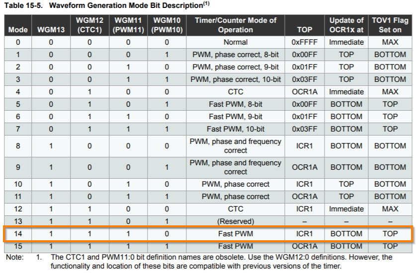
Fast PWM Mode
The fast pulse width modulation or fast PWM mode (WGM13:0 = 5, 6, 7, 14, or 15) provides a high frequency PWM waveform generation option. The fast PWM differs from the other PWM options by its single-slope operation. The counter counts from BOTTOM to TOP then restarts from BOTTOM. In non-inverting compare output mode, the output compare (OC1x) is cleared on the compare match between TCNT1 and OCR1x, and set at BOTTOM.
The PWM resolution for fast PWM can be fixed to 8-, 9-, or 10-bit, or defined by either ICR1 or OCR1A. The minimum resolution allowed is 2-bit (ICR1 or OCR1A set to 0x0003), and the maximum resolution is 16-bit (ICR1 or OCR1A set to MAX).
In fast PWM mode the counter is incremented until the counter value matches either one of the fixed values 0x00FF, 0x01FF, or 0x03FF (WGM13:0 = 5, 6, or 7), the value in ICR1 (WGM13:0 = 14), or the value in OCR1A (WGM13:0 = 15). The counter is then cleared at the following timer clock cycle.
The figure shows fast PWM mode when OCR1A or ICR1 is used to define TOP. The TCNT1 value is in the timing diagram shown as a histogram for illustrating the single-slope operation. The diagram includes non-inverted and inverted PWM outputs. The small horizontal line marks on the TCNT1 slopes represent compare matches between OCR1x and TCNT1. The OC1x interrupt flag will be set when a compare match occurs.

Using the ICR1 register for defining TOP works well when using fixed TOP values. By using ICR1, the OCR1A register is free to be used for generating a PWM output on OC1A.
In fast PWM mode, the compare units allow generation of PWM waveforms on the OC1x pins. Setting the COM1x1:0 bits to two will produce a inverted PWM and an non-inverted PWM output can be generated by setting the COM1x1:0 to three.
The PWM frequency for the output can be calculated by the following equation:

The N variable represents the prescaler divider (1, 8, 64, 256, or 1024). The extreme values for the OCR1x register represents special cases when generating a PWM waveform output in the fast PWM mode. If the OCR1x is set equal to BOTTOM (0x0000) the output will be a narrow spike for each TOP+1 timer clock cycle. Setting the OCR1x equal to TOP will result in a constant high or low output (depending on the polarity of the output set by the COM1x1:0 bits.)
In this case the TOP+1 spike is not a big deal as we are on SSR with Zero-cross function, due to the pike duration nothing will happen on our SSR.
##### TCCR1A/B – Timer/Counter1 Control Register A/B
- TCCR1A Bit 7:6 – COM1A1:0: Compare Output Mode for Channel A
- TCCR1A Bit 5:4 – COM1B1:0: Compare Output Mode for Channel B
The COM1A1:0 and COM1B1:0 control the output compare pins (OC1A and OC1B respectively) behavior. If one or both of the COM1A1:0 bits are written to one, the OC1A output overrides the normal port functionality of the I/O pin it is connected to. If one or both of the COM1B1:0 bit are written to one, the OC1B output overrides the normal port functionality of the I/O pin it is connected to.
When the OC1A or OC1B is connected to the pin, the function of the COM1x1:0 bits is dependent of the WGM13:0 bits setting.

If we refer to what I observed with an osciloscope and what is wrote in section “15.9.3 Fast PWM mode”. Seem that there is a typo in the Microchip ATmega328P datasheet…
- TCCR1A WGM11:0 bits (TCCR1A register) combined with the WGM13:2 bits found in the TCCR1B register, these bits control the counting sequence of the counter, the source for maximum (TOP) counter value, and what type of waveform generation to be used.
-
TCCR1B Bit 4:3 – WGM13:2: Waveform Generation Mode. See TCCR1A WGM11:0 register description.
-
TCCR1B Bit 2:0 – CS12:0: Clock Select

Now we got everything we need !
- TCCR1A
- TCCR1B
- ICR1
- OCR1A
- OCR1B
Just make some code: (undefined bit equal 0)
void setup() {
  cli();          // stop interrupts.
  TCCR1A = 0;     // reset register bits.
  TCCR1B = 0;     // reset register bits.
  TCNT1  = 0;     // reset register bits.

  TCCR1A = _BV(COM1A1) | _BV(COM1B1) | _BV(WGM11);    // COM1A1 and COM1B1 set to "10" inverted mode. WGM11 set to "1" to configure mode 14 "Fast PWM to ICR1".

  TCCR1B = _BV(CS12) | _BV(CS10) | _BV(WGM12) | _BV(WGM13);   // WGM12 and 13 set to "1" to configure mode 14 ( 1110 = "Fast PWM to ICR1"). CS12 and CS10 set to "1" (101 for prescaler 1024), 16Mhz / 1024 = 15.625 KHz
  //

  ICR1 = 6250;  // 15625 / 6250 = 2.5Hz (used to generate the PWM signal frequency, this will allow inclusion of 20 cycles of AC 50Hz).

  OCR1A = 0;    // Set the Output Compare Register 1 A (output A = D9), compare A limit to zero, this result to a PWM duty cycle of 0%. For 10% dc you need to enter 625, for 100% 6250.

  OCR1B = 0;    // (output B = D10).
  sei();        // re-allow interrupts.

  ...

}
- Reset registers bits
- Set COM1A1 and COM1B1 to “1” => COM1A1:0 & COM1B1:0 “10” = Clear OC1A/OC1B on compare match, set OC1A/OC1B at BOTTOM” (inverting mode)
- Set WGM11 to “1”
- Set WGM12 and WGM13 to “1” => WGM13:0 “1110” = “Fast PWM to ICR1”
- Set CS12 CS10 to “1” => CS12:0 “101” = Prescaler “/1024”
- Set ICR1 to “6250”
- Set OCR1A and OCR1B to “0”
This is all that we need to got a PWM fixed period of 2.5 Hz:
- Clock freq / prescaler / ICR1
- 16000000 / 1024 / 6250 = 2.5Hz
And a PWM Duty Cycle for D9 and D10:
- OCR1A
- OCR1B
At any moment set your D9 and D10 PWM dc simply like that :
OCR1A = 3125 // 50 %
OCR1B = 6250 // 100%
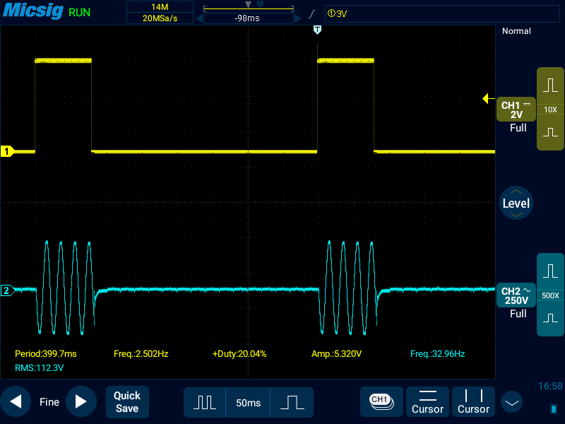
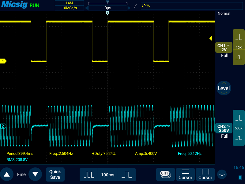
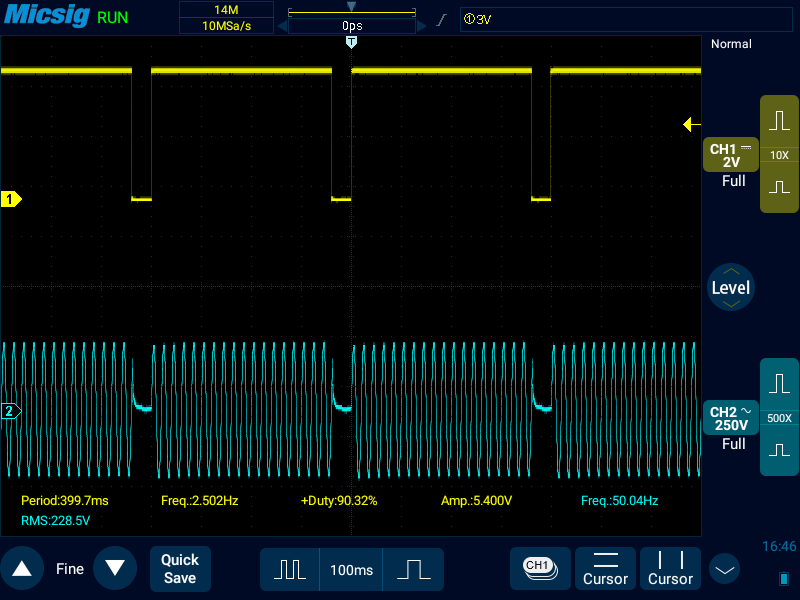
Check measurements I’ve done with my osciloscope: